A 3D Printed Two-Axis Self-Centering Vise
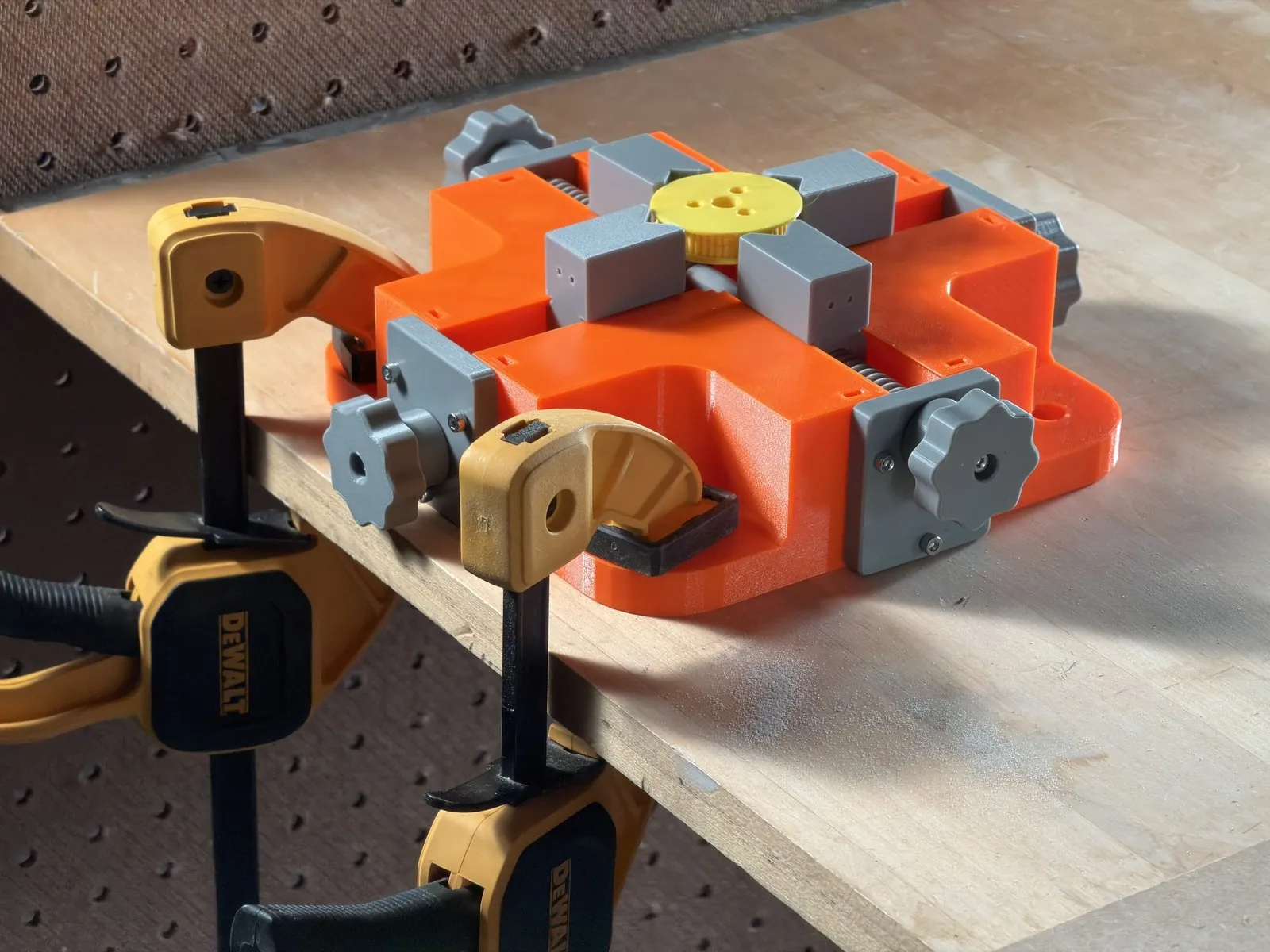
Most vises have a fixed jaw and a moving jaw. You crank the moving jaw in until the part is pinched against the fixed one, so where the part ends up depends on how big it is. A small part sits close to the fixed jaw and a big one sits farther out.
In this vise, both jaws move. Turn a knob and the two jaws move the same amount toward the center, so the part always ends up centered between them. And there are two independent sets of jaws at right angles to each other, each with its own knob. One set centers the part side to side and the other centers it front to back, and the part is held on all four sides.
The advantage is that parts of different sizes all center in the same place. Clamp a 1" block, take it out, clamp a 3" disc, and the middle of each lands on the same spot. If you're drilling on a drill press, you line the vise up once and every part after that is already under the drill.
I set myself a few rules for it: every part 3D printed, and no hardware but M3 screws, nuts and washers. There are no bearings, steel rods, heat-set inserts or glue. Even the lead screws are printed.
Download the vise free on Printables
What it holds
| Square parts | 1" to 4" (25 to 102 mm) |
| Round parts | 0.96" to about 4" (24 to 100 mm) across, centered in V-grooves |
| Jaw height | 3/4" (19 mm) |
| Jaw opening | 0.90" to 4.20" between jaw faces |
| Base | 6.7" (170 mm) square, 1.85" (47 mm) tall |
| Lead screws | printed 1/2" x 8 TPI buttress thread |
| Filament | about 400 g |
| Hardware | 16 M3 x 16 socket head screws, 16 M3 nuts, 16 M3 washers |
It's handy for anything you want centered: marking out the middle of a part, drilling on a drill press, holding a part still to photograph or scan it, or holding a small board to solder. Because the part is held on four sides, you don't need to clamp it very hard.
How the self-centering works
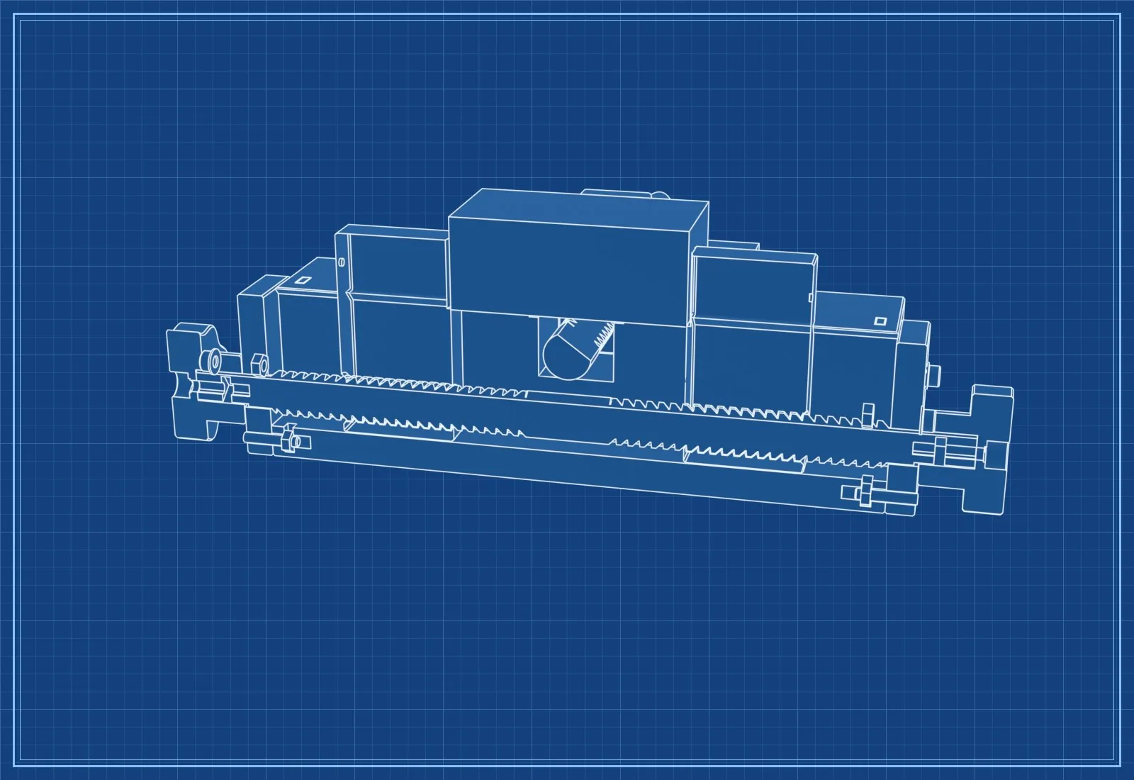
Each pair of jaws runs on one printed lead screw. Half the screw has a right-hand thread and the other half a left-hand thread. Turn the knob and the two jaws move in opposite directions, so they close toward the middle together or open away from it together. The left-hand jaw is an exact mirror of the right-hand jaw, so the pair stays centered wherever you stop.
- Two screws, two heights. The two lead screws cross under the middle of the vise, so one runs about 0.68" (17 mm) lower than the other. In the cutaway above you can see the second screw passing over the first one.
- Jaws that can't run into each other. Every jaw is 0.80" (20 mm) wide, narrower than the smallest part the vise holds, so the four jaws never touch at any setting. Each one slides in a 45° dovetail in the base.
- Stops at both ends. A plain section in the middle of each screw stops the jaws at 0.90" apart. At full open they stop against the end caps.
- A knob on every screw end. There are four knobs, so you can turn either pair from either side of the vise.
Round parts and small boards
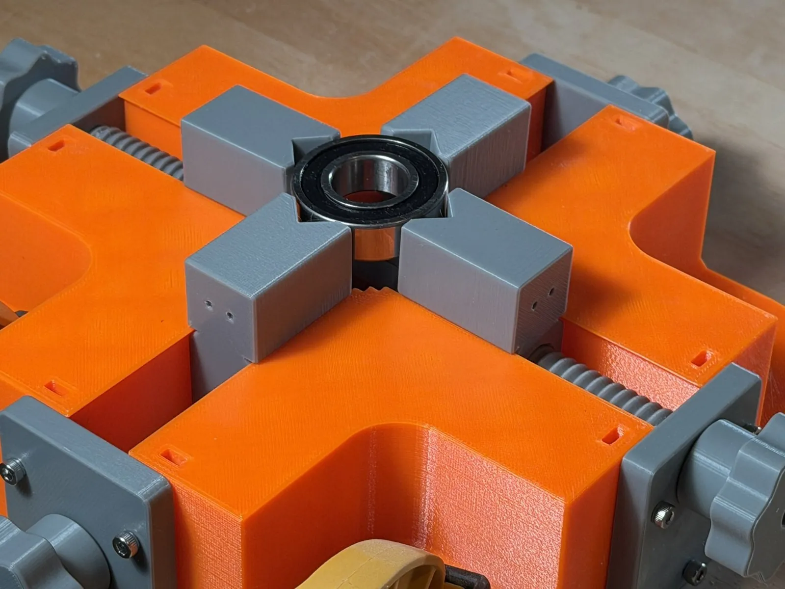
Each jaw face has a vertical V-groove down the middle, so round parts center in it, and flat lands on either side of the V for square parts. A bearing like this one sits in all four Vs at once.
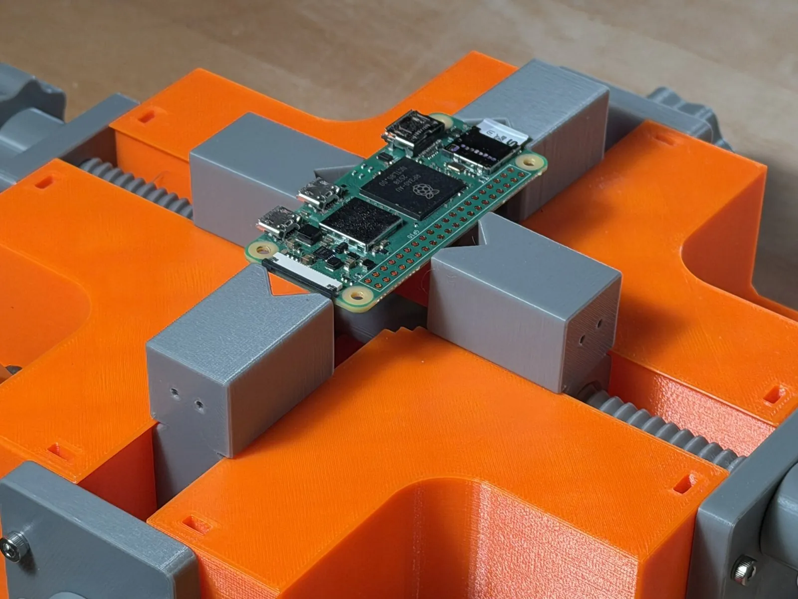
It will also hold a small circuit board like this Raspberry Pi Zero 2 W. I've drawn a second set of jaws just for boards, with a 0.072" (1.8 mm) slot across each jaw face that the edge of the board slides into. They hold boards from about 1" to 4-3/8" with a little over 1/2" of room underneath for parts on the back. I haven't printed them yet, so they'll get their own post.
Holding it down
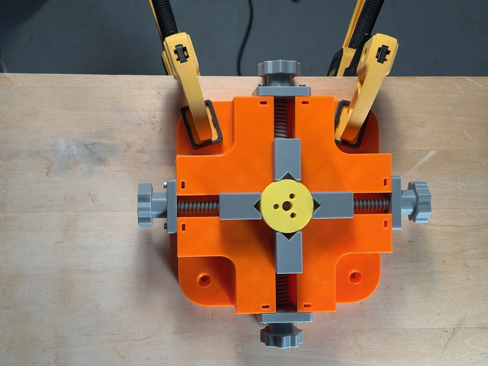
Each corner of the base is cut down to a 1/2" (13 mm) thick ledge, so a bar clamp or C-clamp can grab it without getting in the way of the knobs. If you'd rather screw the vise down for good, each ledge also has a countersunk hole for a #10 flat head wood screw, on a 5" (127 mm) square. Those screws are for the bench, not the vise, so the vise itself still uses only M3 hardware.
Printing it without supports
Every part prints with supports turned off. That took a few tricks:
- The thread. It's a buttress thread, with a steep 7° face that takes the clamping load and a 45° face on the back. The jaws print standing on their jaw face, so inside the nut the steep face points up and only the 45° faces hang over.
- The lead screw. It prints lying down on a flat about 1/8" (3.3 mm) below its center, so every part of the thread leaves the bed at 45° or steeper.
- Sideways holes. These are D-shaped, with a flat top that bridges.
- Edges. Vertical corners are rounded and horizontal edges are chamfered, so elephant's foot doesn't spoil the faces that slide on each other.
- Clearance. Every sliding fit, the threads included, has 0.010" (0.25 mm) of clearance.
The parts go on two plates: the base by itself, then everything else on a second plate. Both fit the 250 x 210 mm bed of my Prusa i3 MK3S, where I printed mine, orange for the base and grey for the rest.
What I changed after the first print
The vise in the photos is my first print, and it taught me a few things. The files have these changes:
- The knob holes didn't open. Each knob is held on by an M3 screw in a counterbore, and I'd covered the screw hole with a one-layer membrane to push the screw through. It printed as a solid floor with no hole. The knobs now have two layers of sacrificial bridging instead. If you printed the old knobs, a 3.5 mm or #29 drill opens them up.
- A shallower V. The Vs in the photos are 90° and 1/2" wide, and a round bar sat on the edges of the V instead of on its faces. They're now much shallower, 0.40" wide and about 1 mm deep, so a 1" bar touches the middle of each face, and bars up to 2" still sit on the faces. The catch is that the jaws print face down, so the V is a very flat roof and the first millimeter droops a little. PrusaSlicer wants supports under 2 layers there. Print it with supports off anyway.
What you'll need
- 16 x M3 x 16 mm socket head cap screws (12 for the end caps, 4 for the knobs)
- 16 x M3 hex nuts
- 16 x M3 flat washers
- A 2.5 mm hex key
- Optional: 4 x #10 flat head wood screws to fix it to a bench
Putting it together
The jaws are marked with dots: 1 dot for the right-hand jaws and 2 dots for the left-hand ones.
- Run each jaw onto its half of a lead screw and back off a few times, until it turns freely.
- Thread the two X jaws onto one screw, one from each end, the 1-dot jaw on the right-hand half and the 2-dot jaw on the left-hand half. Turn them in until they both stop at the middle, then slide the whole thing into the lower channel from one end.
- Do the same with the Y jaws and the second screw in the upper channel. The Y jaws slide over the X screw.
- Drop M3 nuts into the slots in the base and fit each end cap with three screws and washers. The nut for the lower middle screw drops in through the floor of the channel.
- Push a knob onto each screw end. Drop a nut into the slot in the end of the screw, then put a screw and washer through the knob and tighten it.
- Close each pair of jaws on a square block and check that both jaws touch it at the same time.
A little dry PTFE or silicone spray on the threads and dovetails makes it run smoother. It's a printed vise, so it's for holding and locating parts, not for hammering on.
How I designed it
I designed it in Blender, but not by pushing vertices around. I used Claude Code to write a Python script that builds every part from one table of sizes in inches. Each time it runs, it rebuilds the model, checks that no two parts run into each other at six different jaw settings, and exports the STL files. When I wanted something changed, I described it and the script was updated. When I changed something by hand in Blender, like the clamping ledges on the corners, my edits went into the script too, so the next rebuild kept them.
Get the files
The two-axis self-centering vise on Printables. If you print one, please post a Make there and show me what you're holding in it.