
Before you start a model, it is important to know how the model will be used. The end game will determine what software to use, the format of the file created, time saving short cuts that can be taken and how details are constructed.
2D and 3D
2D and 3D models are representations of objects that can be used in computer graphics, animation.
2D models are flat, graphical representations of objects that are created using points, lines, and curves. These models are typically used to create images for user interfaces, games, and other visual media.
Often times, a 2D drawing shows geometry in projected views. With today’s technology, there is still a place for 2D drawings. Not all shops have gone paperless and many skilled people in the trades don’t have the training to utilize 3D models. 2D drawings are frequently printed on large paper and sent to a shop for production and quality control. A 3D drawing, may be displayed on a flat display, but it contains all the information in the 3rd dimension as well.
3D models, on the other hand, are representations of objects that have three dimensions: length, width, and depth. These models are created using polygons, vertices, and edges, and can be manipulated and animated in a 3D space. 3D models are used in 3D printing and to create more realistic images and animations, as they can be viewed from multiple angles and can depict the volume and mass of an object.
Modeling For 3D
There are many forms of 3D modeling. When you model for an artistic purpose, how the model looks on screen is important. When you model for production, dimensional accuracy is important
Modeling for 3D printing is similar to all other production modeling. There are important differences though. When modeling a part that goes to a machine shop, I usually start with a 3D model and then convert the 3D model into a 2D drawing with dimensions and notes. Some details slow down the process and add little to help communicate what the final product needs to look like. For instance, a 2D drawing does not need an accurate representation of the thread in a tapped hole. A simple dashed line with a note does the job. Another short cut is to not draw all the edges accurately. A note that says break all sharp corners will reduce modeling time and improve the display performance.
When modeling for a 3D printer, there are no shortcuts. Threads must be modeled. Edges that are not suppose to be sharp need to be modeled with a bevel.
A model for a 3D printer must not have any holes. Some slicer can fix small holes, but it is much better to not have holes in the first place.
Design considerations for 3D printed parts
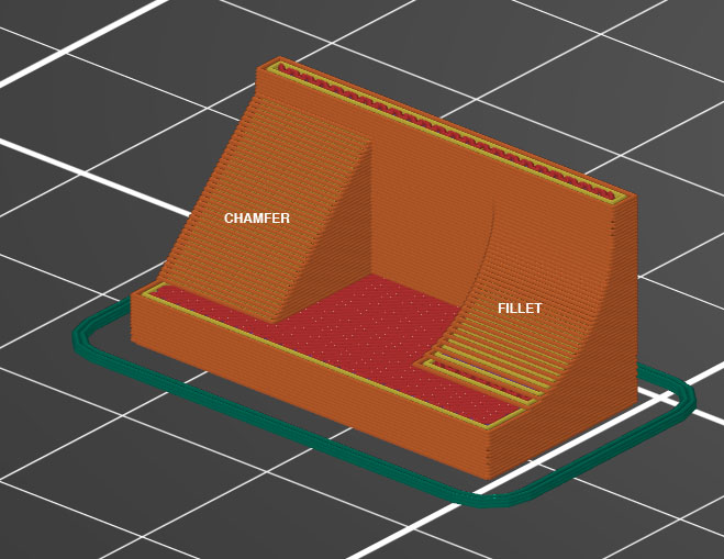
Chamfers and Fillets
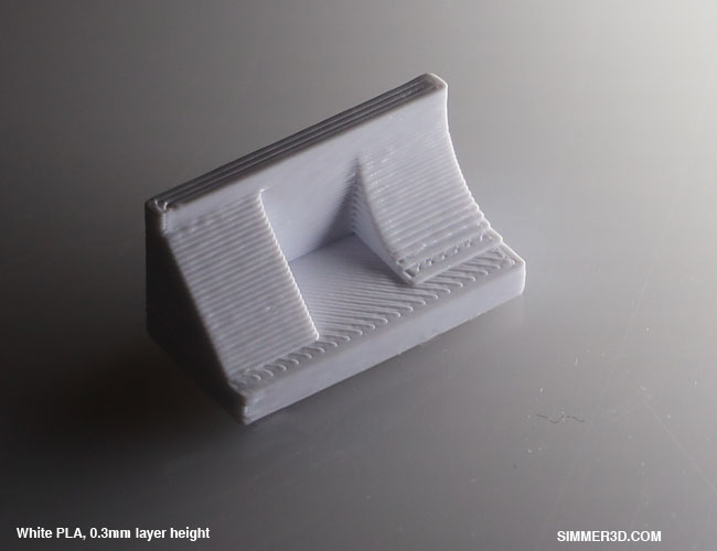
Some design features look good and some don’t. A fillet is the round transition between two surface. A 3D printer can make a nice fillet when the fillet is perpendicular to the nozzle direction. A fillet does not look as good when it is in line with the nozzle. The printer can lay down nice circles, but it does it in layers. At the top and bottom of the arc, the layers are very noticeable.
The alternative to fillets is a chamfer. A chamfer is sloped straight edge between two surfaces. The quality of the chamfer doesn’t change with height.
The images above show a chamfer and a fillet. The layer height was set to 0.3mm (draft mode) to accentuate the issue.
The chamfer looks the same at the bottom and the top. The fillet does not have the same consistency. The slicer was set to make 2 vertical shells. That means the printer makes an outline of the part and then makes a second pass inside that outline. It then fills in the interior of the outline in a zig-zag pattern. This is called the infill. With the fillet design and these slicer settings, infill is exposed. Even if the slicer settings were changed to not expose the infill, there would still be a difference between layer at the bottom of the fillet and the top.
Overhangs
3D printers build up the geometry from a surface. As the printer moves away from the build surface, it uses the geometry below it as a foundation for the next layer. An overhang is an area of the geometry above the build plate where there is no existing geometry below it.
The slicer can add support structures under the overhang. The slicer creates support structure that uses less material than a normal part and it can be easily removed. The support structure usually works, but it is better if the part can be designed so the support structures are not necessary.
3D Modeling Service
Simmer3D is available for hire to model your 3D printed parts. The amount of billable time and time until delivery depends on the complexity of the part, how well the part geometry is communicated to me and my current workload. My rate is $50 per hour with a minimum charge of $20. Use the contact link below to initiate a conversation about modeling your part.
